Since the last update, I've made a few changes to the Millihertz 5 computer, and I've also been working on a document designed for print which gives a high level overview of the machine.
The document is available as a PDF: Offspring PDF or as Pandoc-rendered HTML: Offspring HTML.
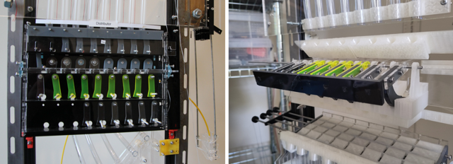
The regenerator now has a completely different design and is separate to the distributor unit. The old regenerator and distributor plate can be seen on the left above, and the new unit on the right. The new distributor unit can be seen on the lower right of the above photos.
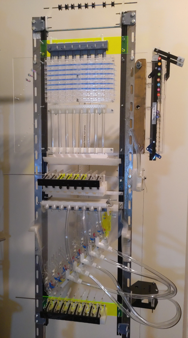
The Accumulator and PC are now mounted front-to-back on the machine. Previously, the program counter (PC) was to be mounted in a separate enclosure, which would have involved a lot of extra pipework to transport ball bearings around, and would have made the machine more difficult to transport. Now, the PC is mounted in front of the accumulator, which makes routing much easier. The downside is that the accumulator value isn't as visible.
The method for conditional signals, that is signals only fire on certain instructions, has been simplified. In the previous version, a 3-to-8 decoder dropped rods into a path to connect a signal path from the camshaft to the output signals; only the fully connected path would transmit any mechanical movement. In the current version, the camshaft followers run directly through the 3-to-8 decoder; signals are sequenced by a drop in the cam level, but the decoder will also prevent 7 of the 8 rods from dropping. Hence, the follower can only drop when the camshaft and the decoder both allow it. This also avoids the need for a separate hold-off signal to lift all the decoder's output rods off the decoders when the decoder rods are moving; the cams just lift all the followers slightly higher.
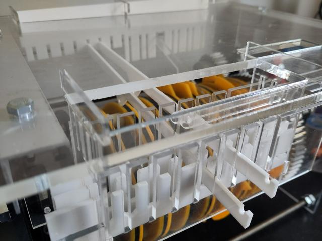
Setting up the rod positions in the instruction decoder has changed. Rather than having a separate mechanism to push rods into position with a ball bearing connecting a mechanical path, the ball bearings now drop directly onto levers and their momentum moves the decoder rods; this feels hacky, but saves a lot of mechanical complication and appears to work reliably with plenty of energy to spare. Resetting all rods back to their start positions still requires a dedicated signal and lever.