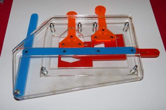
This is a demonstration of an OR gate in sliding plate logic, as used by Konrad Zuse in his Z1 computer. It can be made out of laser-cut acrylic and M3 nuts and bolts.
The inputs to the gate are the two rods on top. These can be pushed upwards (0) or downwards (1). To run a 'clock cycle', the lever on the left should start in the centre, vertical position. It is then pushed fully left and then fully right, then returned to vertical. The output rod on the right will be returned to zero initially, and then pushed right if the output is 1. To chain several of these gates together you'd use a two-phase non-overlapping clock, as you would do with an electrical circuit.
Some features of this design:
It has gain. The output rod's movement is powered both in the 0 and 1 positions and it is powered entirely by the clock lever. It requires less power on the input than it provides on the output - which is necessary if you want to chain several gates together.
Inversion is free on the inputs. By inverting the pattern on the red sliding gates, the inputs can be inverted. This can turn the OR gate into a NAND gate, for example. It would need more modifications to make an AND gate, but these can be made by chaining two gate units together instead.
This is a laser-cut acrylic version which I've made. It needs some manual filing after cutting to make everything work smoothly - one of the biggest problems is the output rod sticking to the blue drive rod because they're too close together.
If you want to try and recreate this, there are OpenSCAD plans and lasercutting files at https://www.github.com/jmacarthur/slidinglogic. The pins used to connect the plates are 3mm diameter and 6mm long steel dowel pins. You can make them yourself by cutting up 3mm rod or screws, but it's difficult to work with such short pieces. Scanning eBay or Amazon in your country will probably find a supplier of metal dowels.