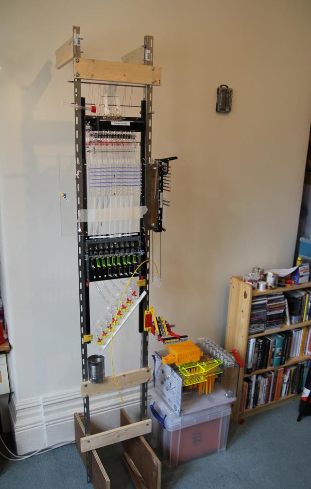
Work is progressing slowly on the Millihertz 5, my all-mechanical implementation of the Manchester Baby. The UK is currently under lockdown, which prevents me accessing the laser cutter in my hackspace, but does give my some time to write documentation. This is an informal discussion of the machine's current state; more formal plans can be found on the Offspring repository on GitHub
From the top down, the metering unit at the top is mostly working, other than being a bit stiff and jamming occasionally. This takes a stream of ball bearings in plastic pipe and meters out exactly eight ball bearings at a time, then distributes them out to the 23mm spacing between columns which the rest of the machine uses.
The top end regenerator - which selectively injects ball bearings into the top of the machine, based on which bearings are present lower down in the machine - has been one of the most difficult things to get working, but the top part of this works fine at least. Most of the datapath works on gravity, so there must be some mechanism to send data upwards at some point. Ball bearings will be physically returned by a lift, yet to be designed, but the information needs to be sent separately using the 'regenerator' mechanism, which uses eight lines of string which are pulled down to send a '1' upwards.
After the regenerator, ball bearings fall into the memory unit, which is also working well. The decoder (the black unit on the right of the machine) decodes the 5-bit address into one of 16 lines; this is chainable so that a second decoder below it can decode the other 16 addresses when we move up to full operation. The "address sender" unit which senses ball bearings and sets up the decoder's address lines must come much lower down, below the instruction counter, and this is posing some problems. The 3mm threaded rods I planned to use become too flexible at the nearly 1 metre length I need, so these may need to be upgraded to a wider hollow tube material.
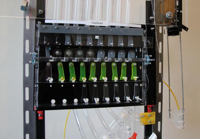
Below the memory is a combination distributor and regenerator; this has to discard memory values (for store instructions), divert the memory value to the instruction counter (for jump instructions) or divert it to the instruction decoder (for instruction fetching). You may be able to see from the picture that two red props have been added which tilt the distributor slightly. This is to help the bearings fall out of the back of the machine, where they would go on to their destination. The slope still isn't enough, and some bearings are failing to fall out and remaining stuck in the distributor.
The regenerator part of this, which senses ball bearings and pulls strings to send data up the machine, is also jamming; the force the strings exert is enough to hold ball bearings in place when they should fall through to the rest of the machine.
The lowest part of the datapath, the staircase subtractor/accumulator unit, is one of the oldest designed parts of the machine, and is working very well. Below this will be another regenerator to send the accumulator's value up to memory. This will be largely the same as the regenerator sender part of the distributor, so I'm leaving it until I get the design of the first regenerator sender working correctly.
Next to the subtractor, there's a temporary Lego contraption with three levers, which is hooked up to various parts near the top of the machine, to test that the parts really do operate by cable/string tension, rather than directly prodding parts.
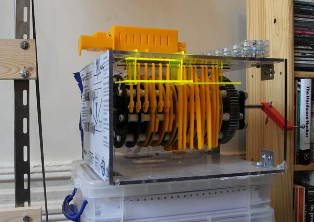
The sequencer is the most current development. This is a large camshaft with 18 cam profiles. The cam profiles are designed to be modular, coming in quarter-circle sections which can be individually replaced. However, they don't snap into place properly and have a tendency to fall out when the bolts holding the whole camshaft together are loosened, so I've had to add some weak glue to hold them in place. The large gear and 14mm diameter shaft have been the most heavyweight engineering I've done on this project, and I'm pleased to say that and the input shaft, reduced 3:1 with a 75:25T gear reduction, are aligned and turning smoothly. A further set of 'combs' on the bottom and the bar which holds the Bowden cables to connect to the followers was designed and ready to cut when I lost access to the laser cutter. The instruction decoder (the yellow box on top of the sequencer) is waiting to be assembled, but is the same design as the memory address decoder, so I'm not expecting any problems with that.
Above the sequencer, the instruction counter and separate metering unit for it still need to be cut, but these are mostly copies of parts already present on the datapath and which work well, so should be straightforward.