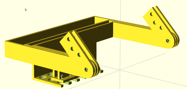
On the left is a rendering of part of my revised Turing machine. The important feature of this, for this post, is that it's a 3D object made up of flat cuboids 3mm thick, which means its parts can be cut out of a sheet of 3mm material by a laser cutter. It's designed (or perhaps written) in OpenSCAD.
Turning this into a 2D drawing to feed into a laser cutter is a manual process at the moment. The best way I've found to do it so far is to comment out all but one top level object at a time, then add an OpenSCAD projection primitive; compile, then export the resulting object as a DXF. This needs to be done for each part, with potentially different projection settings for each, and then the DXFs need to be manually combined.
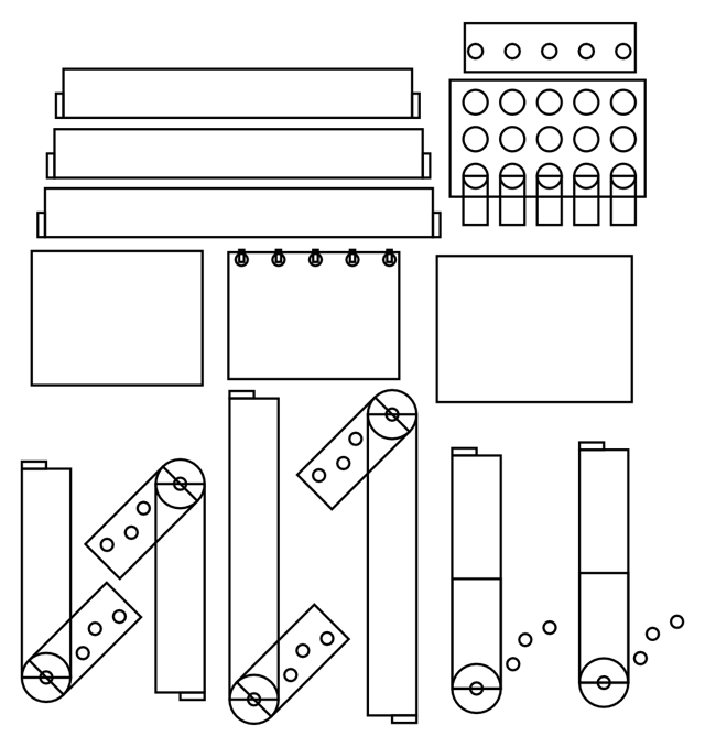
This next picture is a rasterized SVG which was produced by a perl script I wrote to do this job automatically. The only post processing I've done is to move the top level objects around, as they end up on top of each other at the moment, and to increase the line width. As you can see, this is not perfect, as there are more cut lines there than there should be, but it is automatic. Another advantage of this method is that the produced diagram has true circles in it, rather than the polygonal approximations OpenSCAD produces. The script won't work on objects that are not within a thin plane; the model shown was already split into those objects and had the tabs added by hand. This script is just doing the job of rearranging objects into 2D form.
I am hoping to get the Clipper library involved next to do 2D unions and intersections necessary to produce useful laser cutter drawings. This library can also do outsetting, which will be useful to correct for the diameter of the cutting beam. (Inkscape can do outsetting too, but there is a bug in the current implementation relating to small lines at right angles.) For example, the tabs on the end of the thin bars shown above should be part of the same object. The script knows that these are part of a union, so should be union'ed in 2D to remove the line separating them.
There are of course restrictions in what this can produce; it's limited to orthogonal cubes, cylinders and polygons. Anything that produces an edge not perpendicular to the plane of the object will not work, but then it couldn't be produced by a normal laser cutter anyway. It shouldn't be limited to orthogonal planes - any orientation should work, although I've not tried it with non-orthogonals yet.
This perl script runs from the processed CSG output from OpenSCAD. This is thankfully very easy to parse. I used Parse::RecDescent to parse it. Then there are several passes of tagging elements in the tree and determining which shapes are positives and which are subtracted from the original solid; then a lot of matrix maths to identify top level objects which all fit into a 3mm thick plane segment and to project all its components into the same 2d plane. I hammered out the perl script in one day, and it's full of bugs and very badly written, so I'm not going to publish it right now. If anyone is interested in it, I'll tidy it up and open source it.