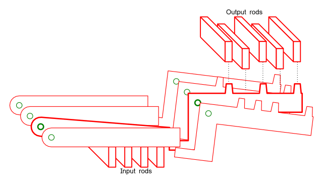
The decoder logic I described in the previous post can be used as part of an array logic device. Each output rod from the decoder needs to raise a selected set of output rods, which can then be driven by another power source.
As in thje decoder logic, one lever can drop into a slot made by the arrangement of input rods. The output cranks will usually fall down, but in the one row where the input lever has fallen, the output crank will be blocked, and continue to stay in the raised position.
Output rods then run across all the output cranks. they will be lifted by the one output crank which is raised. The output cranks have a pattern on bumps on top, which will determine which outputs are raised.
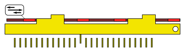
The output rods, raised (or not) by the output cranks, are driven by the red plate shown in this diagram. If an output rod is raised, it will be caught by the drive plate and pushed forward when the drive plate is pushed forward. The second, higher step always catches the drive plate when the drive plate is pushed back, so all rods return to zero in the first part of the cycle.
One end of the output rod can then be attached to a Bowden cable interconnect.
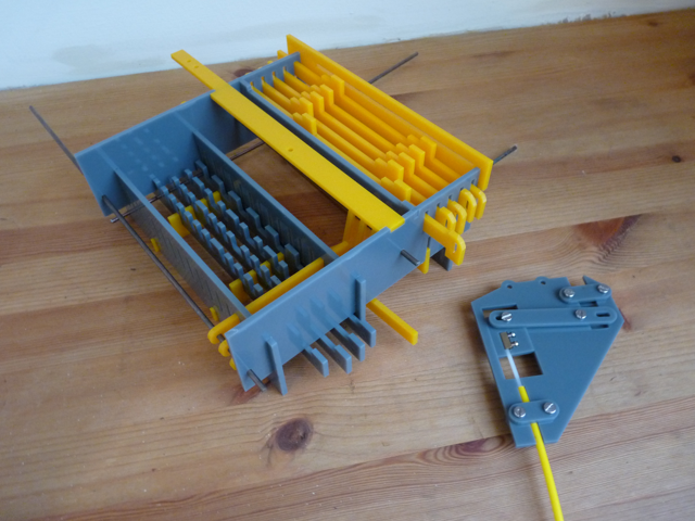
I've made two prototypes of this at Trafford FabLab in Altrincham. Neither are quite working correctly, but they are close enough to prove the concept.
The following image is the first prototype. The input levers have been removed (the same parts were re-used for the second prototype) so you can see the pattern on the input rods.
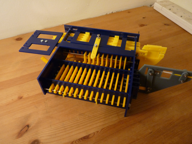
The next image is the more complete second prototype. This shows the drive plate on top and the bracket (top left) used to connect Bowden cables to so the drive plate can be driven. On the right hand side, two Bowden connectors are attached, one driving one input and one driven by one output.
Once developed until they are highly reliable, large numbers of these units could be used to create any boolean logic circuit. Since each functions as a register as well (the output is only updated when the output drive is cycled) they can create latched logic using a two-phase clock. The only parts missing are a fan-out connector, to connect one output to several inputs, and the cams necessary to run the various sequence levers.
This scheme should enable a fairly rapid gate propagation time, but even so, creating a binary adder with this technology will lead to large delays. Also, constructing memory from these systems would be very inefficient in terms of the number of parts. Handily, there are shortcuts for both of those which I'll write about soon.
The machines pictured here were cut using a laser cutter at Trafford FabLab which is an excellent resource for anyone wanting to make physical prototypes.